Optical Profilometer March 14, 2018
I’m building an optical profilometer. Made with a microscope, a projector, a camera, and a computer vision algorithm, it will measure the three dimensional topography of a sample by repeatedly imaging the sample at different heights, and measuring when each region of the sample crosses the microscope’s focal plane.
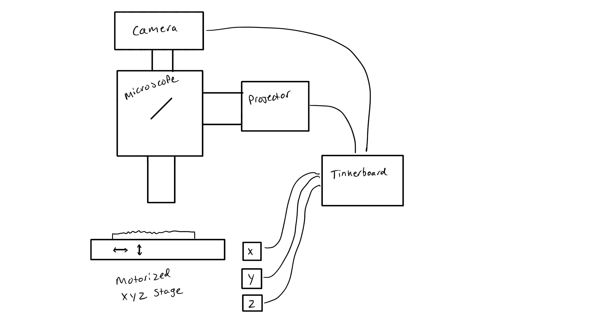
The idea is this:

The machine will be built around a metallurgical fluorescence microscope such as this one, which features a UV source, a camera, and a high-precision XYZ stage. The UV source will be replaced with an inexpensive low-resolution pico DLP projector, interface optics TBD. Since motorized microscope stages are super expensive, I’ll mechanize the stage on the microscope with NEMA 17 stepper motors, which I’ll hook up using GT2 belts and custom designed and printed pulleys. These will be controlled by a custom board, using the A4988 stepper drivers familliar to the 3D printer world.
All of this will be driven by a Tinkerboard, a souped-up RasPi clone with a bit more processing and graphics oomph. Its GPIO will drive the motors, the camera will connect by USB, and it will interact with the outside world through WiFi.
The software will consist of three basic parts, beginning with an electron app, running on Linux on the Tinkerboard, which will do most of the work. It will handle the basic operations of the machine—graphics output, image capture, motor control—as well as higher level functionality, such as machine vision, constructing the final mesh, and executing the program that runs through the entire imaging process. A simple firebase backend will connect this to an Angular web app with which the user will control the machine via the internet.